Understanding Inductor Symbols
Overview of Inductor Symbols
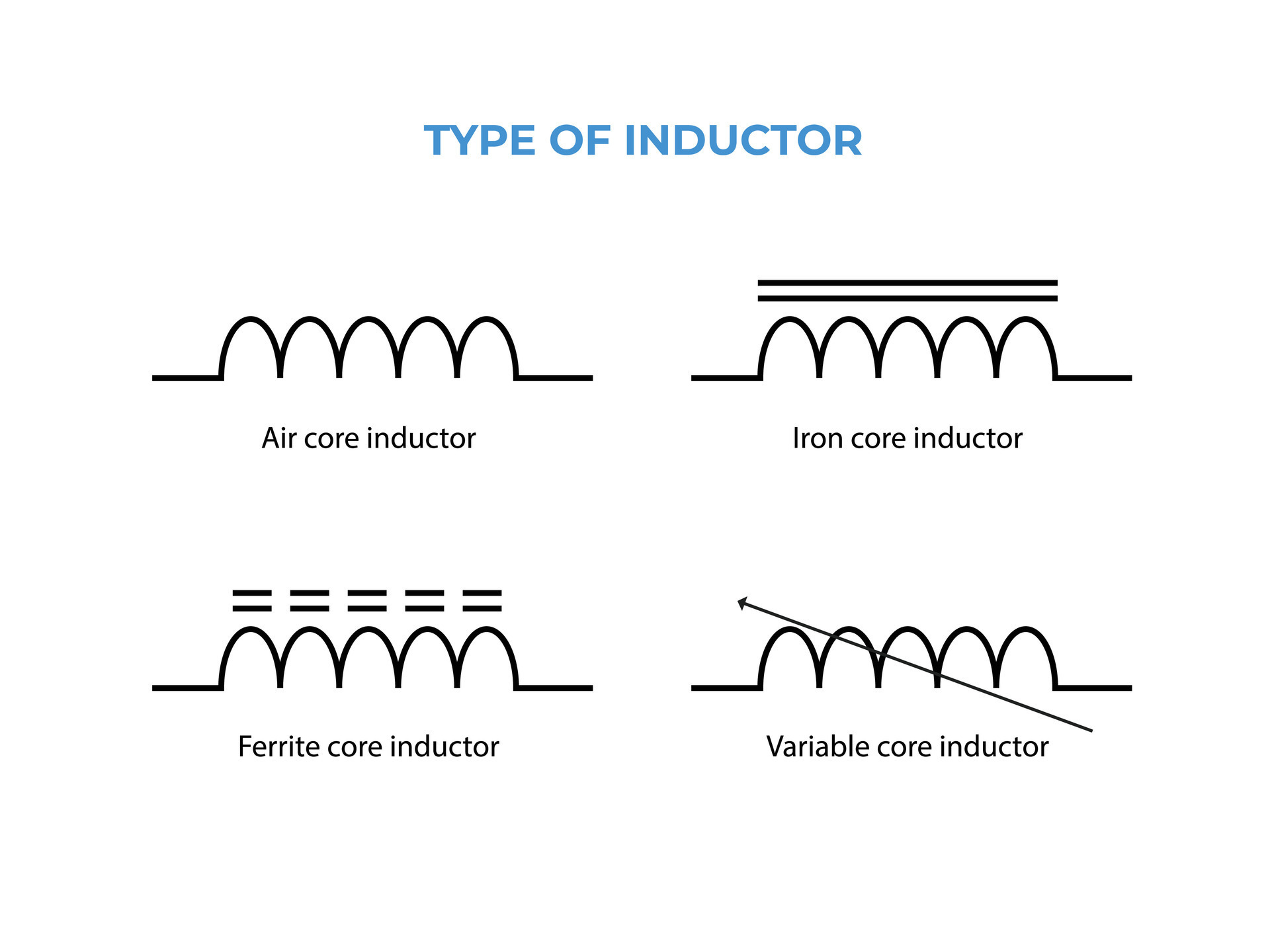
In the realm of electronics, inductor symbols hold significant importance as they visually represent the functionality of inductors within circuit diagrams. Whether it's a fixed inductor denoting a set inductance value or a variable inductor allowing for inductance changes during operation, these symbols serve as a key aspect in circuit design.
Solenoid, Choke, and Coil Symbols
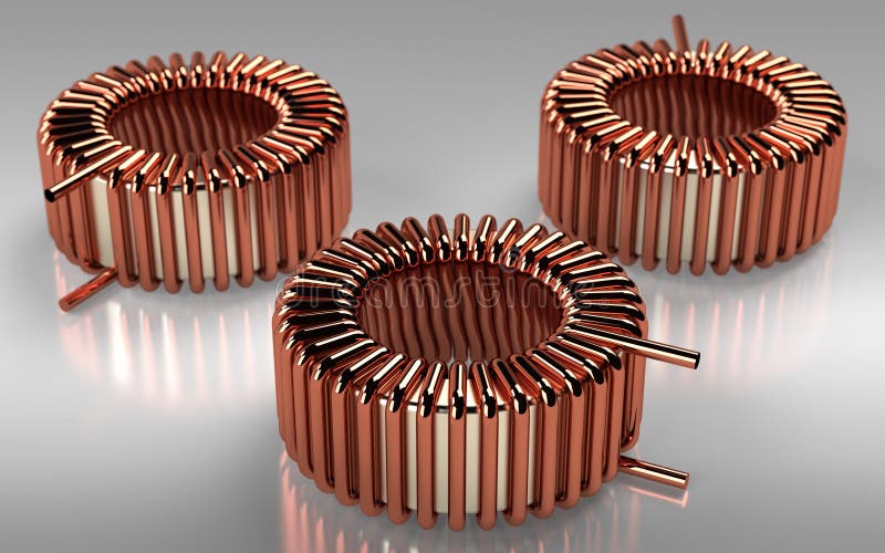
Symbols such as solenoids, chokes, and coils are interchangeably used to represent inductors in schematics. The solenoid symbol typically signifies a coil of wire, while chokes are essential in filtering out unwanted signals. Coils play a vital role in storing energy within a magnetic field.
Importance of Inductor Symbols in Circuit Diagrams
The accurate utilization of inductor symbols helps in conveying the inductance properties and functions effectively in circuit diagrams. Understanding these symbols aids in proper circuit analysis and design, ensuring the smooth operation of electronic systems.

Types of Inductor Symbols
Solenoid Symbol Representation
In the realm of electronics, solenoid symbols visually depict a coil of wire within circuit diagrams. These symbols are vital in illustrating the presence of inductors and their magnetic field storage capacity.
Chock and Coils Symbol Variations
Symbols for chokes and coils play a crucial role in representing inductors in circuit diagrams. Chokes aid in filtering unwanted signals, while coils store energy within magnetic fields. Understanding the variations in these symbols is essential for accurate circuit analysis and design.
Generic Fixed Inductor Symbol
Explanation of Generic Fixed Inductor Symbols
When examining circuit diagrams, the representation of a fixed inductor through symbols is crucial. These symbols, often denoting a coil or choke, convey the presence of components with a steady inductance value.
Significance of Representing Inductors with Fixed Values
Using symbols to indicate fixed inductors aids in understanding circuit behavior and analyzing electromagnetic interactions accurately. It provides a concise and standardized method for engineers to portray components within electronic systems.

Variable Inductor Symbol
Variable Inductor Representation in Circuit Diagrams
In circuit diagrams, the symbol for a variable inductor is crucial for illustrating components with adjustable inductance levels. This representation allows engineers to visually understand where inductors with variable characteristics are utilized within a circuit.
Application and Functionality of Variable Inductors
Variable inductors play a significant role in circuits like radios, where the ability to modify inductance during operation is essential. Their application aids in tuning circuits, allowing for precise adjustments to meet specific performance requirements.

Inductor with Polarity Symbol
Concept of Polarity in Inductor Symbols
In circuit notations, the presence of a dot on one side of the terminal in an inductor signifies polarity. This convention indicates the direction of current flow into the inductor, facilitating optimized mutual inductance in applications involving coupling of inductors. Polarity symbols are crucial in circuit design for ensuring the correct orientation and utilization of inductors within electronic systems, thereby contributing to efficient operation and signal processing capabilities. The polarity indication aids engineers in configuring circuits accurately, promoting effective integration of inductors into various electronic devices.