
Resistor Symbols Overview
Understanding Resistor Symbols
In the context of electrical engineering, resistor symbols play a crucial role in circuit diagrams. They represent various types of resistors used in electronic circuits. These symbols provide a standardized way of depicting resistors, making it easier for professionals to interpret circuit designs accurately.
NEMA & IEC Systems
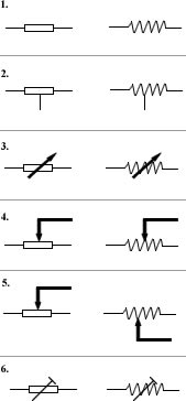
In both the NEMA and IEC standards systems, resistor symbols are used to denote fixed resistors. The NEMA and IEC symbols for resistors differ slightly but serve the same purpose of representing fixed resistors in circuit diagrams. Understanding these symbols is essential for designing and analyzing complex electronic circuits.

Variable & Adjustable Resistors Symbols
Variable Resistor Symbol
In the realm of electrical engineering, the symbol for a variable resistor signifies a component whose resistance value can be adjusted manually to control the flow of electric current in a circuit. This symbol typically resembles a regular resistor with an arrow or a diagonal line across it, indicating its adjustability.
Adjustable Resistor Symbol
The symbol for an adjustable resistor, also known as a potentiometer, depicts a resistor with an arrow pointing towards a curved line. This symbol denotes a resistor whose resistance can be varied continuously within a specific range by adjusting a knob or slider. Understanding these symbols is vital for accurately representing these types of resistors in circuit diagrams.

Special Resistor Symbols
Symbols for Special Resistors
Special resistors, like light-dependent resistors or thermistors, have unique symbols used in circuit diagrams. These symbols represent components that exhibit specific properties under varying conditions, such as light intensity or temperature.
Attenuator Symbol
An attenuator symbol in circuit diagrams signifies a component that reduces signal power without causing distortion. It is represented by a specific graphical symbol that distinguishes it from other types of resistors or components. Understanding and recognizing these symbols is crucial for accurately designing and analyzing circuits.
IEEE & IEC Symbols of Resistors
Understanding IEEE Symbols
IEEE symbols for resistors are standardized graphical representations that help in identifying different types of resistors in circuit diagrams. These symbols follow specific conventions set by the Institute of Electrical and Electronics Engineers (IEEE) to ensure clarity and consistency in circuit schematics.
Understanding IEC Symbols
IEC symbols for resistors are internationally recognized symbols that adhere to standards set by the International Electrotechnical Commission (IEC). These symbols are used to depict various types of resistors in circuit diagrams, allowing engineers and technicians across different countries to easily interpret and work with electrical circuits.
Conclusion
Recap of Resistor Symbols
The IEEE and IEC symbols for resistors play a crucial role in circuit design and understanding schematic diagrams. These standardized graphical representations help in identifying different types of resistors, such as fixed, variable, adjustable, and special resistors, in electrical circuits. By following specific conventions set by IEEE and IEC, engineers and technicians can easily interpret circuit diagrams.
Importance of Understanding Resistor Symbols
Understanding resistor symbols is essential for professionals working in the field of electronics and electrical engineering. It enables them to accurately design circuits, troubleshoot issues, and communicate effectively with others in the industry. By knowing the meaning and representation of resistor symbols, individuals can ensure the proper functioning and safety of electronic devices and systems.