
Introduction to Boost Converter
What is a Boost Converter?
A Boost Converter is a type of DC-DC converter that increases the voltage level of the input supply to a higher level at the output. It is commonly used when the required output voltage is higher than the input voltage provided by the power source.
Principle of operation of a Boost Converter
– The Boost Converter operates on the principle of energy storage and transfer.- During operation, the input voltage is stored in an inductor and then released to the output capacitor to achieve a higher voltage output.- The switching element in the circuit controls the energy transfer process, regulating the output voltage level.

Understanding Boost Converter Circuit
Components of a Boost Converter Circuit
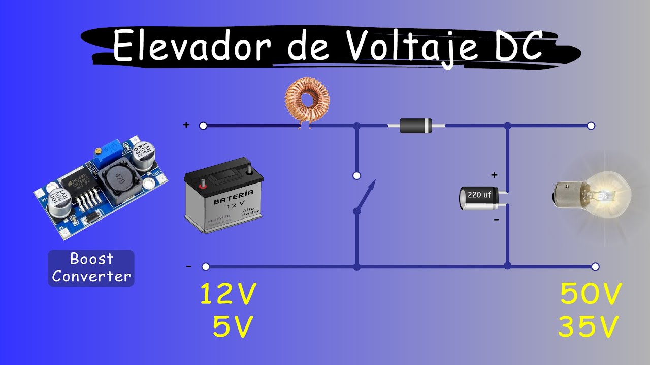
– Inductor: Stores and releases energy between input and output.- Diode: Controls the direction of current flow.- Capacitor: Smoothens the output voltage.- Switching Element: Controls energy transfer process.- Load: Receives the boosted output voltage.
Basic Boost Converter Circuit Diagram
| Component | Description |
|---|---|
| Input Voltage Source | Provides the initial voltage input. |
| Inductor | Stores energy from the input. |
| Switching Element | Controls the energy transfer process. |
| Diode | Directs the energy flow towards the output. |
| Capacitor | Filters and stabilizes the output voltage. |
| Output Voltage (Load) | Receives the boosted voltage for use in the circuit. |
Boost Converter Working Mechanism
Input and output voltage relationship
The Boost Converter circuit increases an input voltage to a higher output voltage, allowing compatibility with devices requiring a greater voltage level. This is beneficial when dealing with battery limitations or specific component requirements.
Switching operation in a Boost Converter
During operation, the switching element in a Boost Converter rapidly switches the input voltage on and off. This process helps in transferring energy to the inductor, which subsequently boosts the voltage level required by the load. The diode ensures the directed flow of energy towards the output, providing a stable and continuous power supply.
Design and Construction of Boost Converter
Steps to construct a Boost Converter
– Start by gathering necessary components: inductor, diode, capacitor, and switch.- Connect the components according to the Boost Converter circuit diagram.- Ensure proper insulation and secure connections for safety.- Test the circuit with a multimeter to verify voltage output.- Fine-tune the components for optimal performance.
Factors to consider in Boost Converter design
– Select components with appropriate voltage and current ratings.- Consider efficiency and heat dissipation for long-term operation.- Calculate component values based on desired output voltage and current.- Account for voltage spikes and protection mechanisms in the design.- Optimize the layout for compactness and ease of assembly.

Efficiency and Performance of Boost Converter
Efficiency calculation in Boost Converters
– Efficiency of a Boost Converter is calculated by dividing the output power by the input power, then multiplying by 100%.- Efficiency = (Output Power / Input Power) x 100%.- Higher efficiency indicates less power loss during voltage conversion, leading to better performance.
Impact of load variations on Boost Converter performance
– Load variations affect the performance of a Boost Converter by influencing the output voltage stability.- Sudden changes in load can result in voltage fluctuations and affect the overall circuit operation.- Design considerations should include provisions for handling varying loads to maintain stability and efficiency.