Introduction
Cable and Wire Tester Circuit Diagram Overview
– Cable testers are essential electronic devices for checking signal cables and wired assemblies.- They ensure path connectivity and detect any improper connections.- By assessing communication strength from source to destination, cable testers guarantee reliable data transmission.
Multi Electronic Tester Breaking News
– The Multi Wire and Cable Electronic Tester Circuit Project offers advanced cable testing functionalities.- It enhances signal cable reliability by providing detailed insights into signal strength and connectivity.- This project caters to the growing demand for efficient cable testing solutions in various industries.

Basics of Cable Testing
Understanding the purpose of cable testers
– Cable testers play a crucial role in assessing the integrity of signal cables and wired assemblies.- These devices are indispensable for verifying path connectivity and detecting any faulty connections.
Path connectivity and signal strength
– Cable testers ensure that data transmission occurs smoothly from the source to the destination.- The Multi Wire and Cable Electronic Tester Circuit Project is designed to meet the increasing demand for efficient cable testing solutions in various industries.

Components Used
IC 4017 explanation
– The IC 4017 is a versatile component commonly used in electronic projects.- It is a 16-pin counter/divider integrated circuit that can operate in multiple modes.
Working of IC 4017 in the circuit
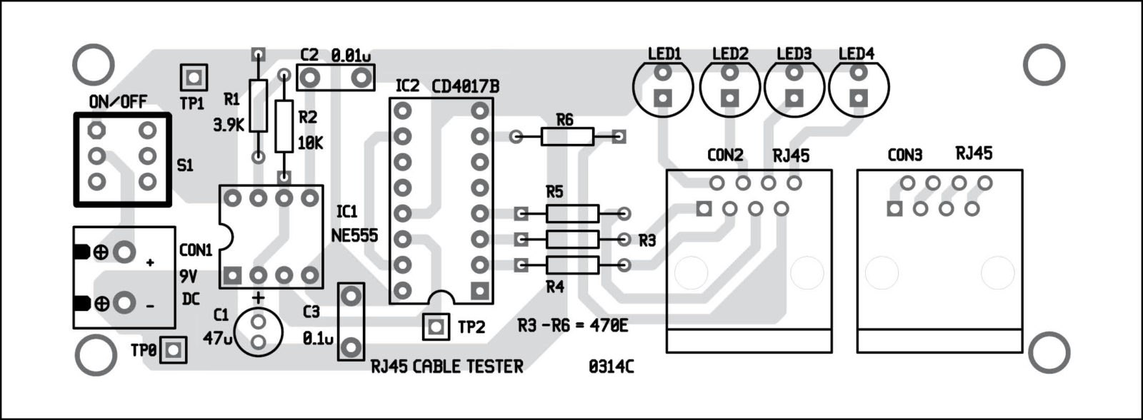
– In the Multi Wire and Cable Electronic Tester Circuit Project, the IC 4017 plays a key role in controlling the sequence of outputs.- Through its unique configuration, it helps in generating the desired signals for testing cable connectivity and strength.

PWM Signal Generation
555 timer IC utilization
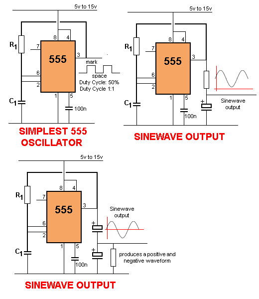
– The 555 timer IC is a widely used component in electronic circuits.- It is commonly employed for generating precise and stable time delays or oscillations.
Generating PWM signal for IC 4017
– In the Multi Wire and Cable Electronic Tester Circuit Project, the PWM signal is crucial for controlling the IC 4017.- By modulating the width of the pulse, the PWM signal assists in producing varying output voltages.
The PWM signal is a pivotal aspect of the circuit design as it aids in effectively controlling the operation of the IC 4017 for accurate testing of cable connectivity and strength.

Circuit Design and Implementation
Detailed explanation of the cable tester circuit design
- The 555 timer IC plays a pivotal role in the circuit, serving as a reliable component for generating precise time delays and stable oscillations.
- Significant emphasis is placed on the generation of a PWM signal, critical for controlling the IC 4017 within the circuit.
Step-by-step implementation process
- The implementation of the Multi Wire and Cable Electronic Tester Circuit Project involves carefully integrating the 555 timer IC for PWM signal generation.
- The modulation of pulse width is crucial for producing varying output voltages, ensuring effective testing of cable connectivity and strength.