Introduction
Overview of LED Roulette Circuit
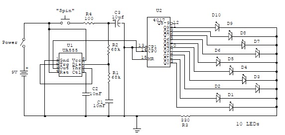
– The LED Roulette circuit is designed to mimic the functioning of a roulette wheel game found in casinos.- This circuit integrates a 555 timer IC and a CD4017 counter IC to create a dynamic flashing LED pattern.- By simulating the randomness of a roulette game, this circuit provides a visually appealing lighting display.
Explanation of Timer 555 and Counter 4017
– The 555 timer IC serves as the clock pulse generator in the circuit, controlling the timing and frequency of the LED flashes.- The CD4017 counter IC acts as a decade counter, sequentially activating the LEDs in a pattern to simulate the spinning motion of a roulette wheel.- Together, these components work in tandem to create an engaging and entertaining LED display.

Circuit Components
555 Timer IC and its Function
– The 555 timer IC acts as the clock pulse generator for the LED Roulette circuit.- It controls the timing and frequency of the LED flashes, contributing to the dynamic lighting pattern.
4017 Counter IC and its Role
– The 4017 counter IC functions as a decade counter within the circuit.- It sequentially activates the LEDs in a pattern that simulates the spinning motion of a roulette wheel.
Circuit Design
Step-by-Step Guide to Circuit Design
– Using the 555 timer IC to generate clock pulses, start by connecting pin 2 to ground, pin 4 to VCC, and pins 2 and 6 together for trigger and threshold control. – Integrate the 4017 counter IC by connecting pin 16 to VCC, pin 8 to ground, and connecting the output pins to LEDs to enable sequential lighting.
Connection setup of LEDs in the Circuit
– Connect LEDs to the output pins of the 4017 counter IC, ensuring that each LED corresponds to a specific output pin.- Optimize the LED placement for a visual roulette wheel effect, simulating the rotation pattern through sequential lighting.

Operation
Functioning of Timer 555 in the Circuit
In the LED Roulette circuit design, the 555 timer IC serves the crucial function of generating clock pulses. The timer is configured by connecting specific pins to control trigger, threshold, and power supply. This setup ensures the consistent generation of clock signals required for the circuit's operation.
Role of Counter 4017 in LED Sequence
The 4017 counter IC plays a significant role in the LED sequence of the circuit. By connecting the output pins of the 4017 to individual LEDs, the counter enables sequential lighting patterns. Each LED corresponds to a specific output pin, creating the visual effect of a rotating roulette wheel as the LEDs light up in succession.
Advantages and Applications
Benefits of LED Roulette Circuit
– The LED Roulette circuit provides an engaging visual display reminiscent of a roulette wheel, making it an attractive project for electronics enthusiasts and hobbyists.- It offers a hands-on learning experience for understanding the functionalities of ICs like the 555 timer and 4017 counter in a practical setting.- The circuit's simple design allows for customization and modifications, providing room for experimentation and creativity in LED sequencing.
Practical Uses and Applications
– Educational purposes: Suitable for electronics students to comprehend timer and counter IC applications.- Entertainment: Can be utilized as a decorative piece or prop for gaming-themed events.- Prototyping: Offers a foundation for developing more complex LED sequencing projects and light displays.