Introduction to Components of Admittance
Explanation of Admittance and its components
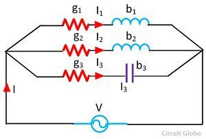
In the realm of electrical circuits, conductance, represented by G, aligns with the applied voltage, while susceptance, denoted by B, stands at a right angle to it. Conductance is measured in Mhos or Siemens, mirroring how well the circuit allows current flow. Simultaneously, susceptance gauges the circuit's reactance to the applied voltage.

Conductance in Admittance
Definition and calculation of conductance in admittance
In the domain of electrical circuits, conductance, denoted by G, pairs with the applied voltage to measure the ease of current flow. It is quantified in Mhos or Siemens. Conductance serves as a pivotal component in evaluating how well a circuit facilitates the movement of electrical current.

Susceptance in Admittance
Understanding and calculation of susceptance in admittance
Within electrical circuits, susceptance, symbolized as B, emerges orthogonal (at 90 degrees) to the applied voltage. It is gauged in Mhos or Siemens. Susceptance plays a crucial role in determining how well a circuit enables the passage of electrical current.

Total Conductance and Susceptance
Explanation of total conductance and total susceptance in admittance
Conductance, denoted as G, is the component inphase with the voltage in admittance. On the other hand, susceptance, represented as B, is orthogonal to the applied voltage. Total conductance and susceptance play crucial roles in determining the efficiency of electrical current flow within a circuit.

Significance of Components
Importance of conductance and susceptance in electrical circuits
Conductance, labeled as G, aligns with the voltage in admittance while susceptance, denoted as B, is perpendicular to the applied voltage. Total conductance and susceptance are vital in regulating the effectiveness of electrical current flow within circuits.

Inductive and Capacitive Susceptance
Difference between inductive and capacitive susceptance in circuits
In electrical circuits, inductive susceptance (denoted as -jB) is characteristic of inductive components, while capacitive susceptance (denoted as +jB) is specific to capacitive elements. These values play a crucial role in determining the behavior of current flow in the circuit.

Formulas in Admittance
Key formulas related to conductance and susceptance in admittance
Inductive and Capacitive Susceptance
Difference between inductive and capacitive susceptance in circuits
In electrical circuits, inductive susceptance (denoted as -jB) is characteristic of inductive components, while capacitive susceptance (denoted as +jB) is specific to capacitive elements. These values play a crucial role in determining the behavior of current flow in the circuit.

Practical Applications
Real-life applications of understanding components of admittance
Inductive and capacitive susceptance values are crucial in analyzing circuit behavior. Inductive susceptance (-jB) and capacitive susceptance (+jB) are key components influencing current flow. Understanding these values helps in designing efficient electrical circuits.

Conclusion
Summary of key points and significance of learning about components of admittance
Real-life applications of understanding components of admittance are evident in designing efficient electrical circuits. Inductive and capacitive susceptance values significantly influence current flow, making them crucial in circuit analysis. By grasping these components, individuals can enhance their circuit design skills and ensure optimal performance in electrical systems.