Introduction
Overview of Voltage Tripler Circuit
The voltage tripler circuit is a configuration that triples the input voltage by using diodes and capacitors. It falls under the category of multiplier circuits that can deliver output voltage two, three, or four times the peak input voltage. This circuit is commonly employed when high voltage and low current are required in various electronic applications.
Importance of Voltage Tripler Circuits
Voltage triplers are significant in situations where high voltage levels are needed while minimizing the current flow. They are particularly useful in scenarios where transformer size reduction or elimination is desired. This circuit design offers a convenient and straightforward approach to achieving triple the input voltage output.

Basics of Voltage Multipliers
Explanation of Voltage Multipliers
Voltage multipliers, such as the voltage tripler circuit, utilize diodes and capacitors to increase the output voltage to two, three, or even four times the peak input voltage. These circuits are commonly employed in applications that necessitate high voltage and low current requirements.
Difference between Voltage Doubler and Voltage Tripler Circuits
Voltage doublers double the input voltage, while voltage triplers triple the input voltage. The main distinction between the two circuits lies in the multiplication factor they offer. Voltage doublers are used when twice the input voltage is required, whereas voltage triplers are utilized to achieve three times the peak input voltage.

Components Needed
List of Components for Voltage Tripler Circuit
– Diodes- Capacitors
Purpose and Role of Each Component
– Diodes: Used to rectify the input voltage and prevent current flow in the reverse direction.- Capacitors: Store and release electrical energy, helping to smooth out the output voltage in the circuit.
Voltage multipliers, like the voltage tripler circuit, employ diodes and capacitors to amplify the output voltage to two, three, or four times the peak input voltage. These circuits find applications in scenarios requiring high voltage and low current demand. Voltage doublers double the input voltage, whereas voltage triplers triple it, offering different multiplication factors based on the circuit utilized.

Voltage Tripler Circuit Diagram
Step-by-Step Guide to Building Voltage Tripler Circuit
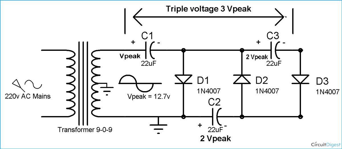
– Gather components: Diodes, Capacitors- Connect diodes and capacitors in specified configuration- Input AC signal into the circuit- Output voltage will be three times the peak input voltage
Visual Representation of Circuit Diagram
– Diodes and capacitors arranged in a specific pattern- Input and output points clearly marked- Electrical symbols used to represent components
The Voltage Tripler Circuit utilizes diodes and capacitors to amplify voltage output. This circuit is commonly employed in situations requiring high voltage and low current. By tripling the input voltage, it offers increased voltage levels for various applications.
Working Principle
Understanding How Voltage Tripler Circuit Works
The Voltage Tripler Circuit functions by utilizing diodes and capacitors to triple the input voltage, delivering three times the peak input voltage at the output. By connecting the components in a specific configuration and inputting an AC signal, the circuit is able to amplify the voltage effectively.
Explanation of Voltage Tripling Process
The voltage tripling process involves the strategic arrangement of diodes and capacitors to magnify the voltage output. This method is commonly used in scenarios where high voltage and low current are required, enabling the circuit to enhance voltage levels for diverse applications.