_iSYfU9NlwL.jpg)
Introduction
Overview of Car Speed Detector Circuit
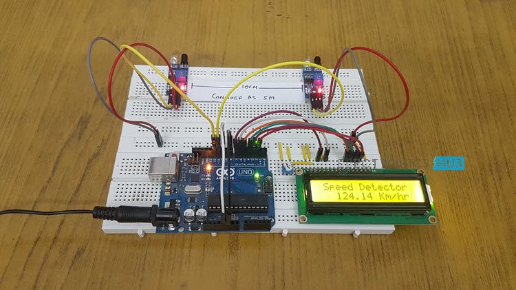
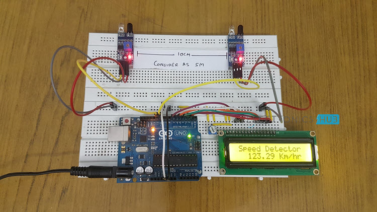
The Car Speed Detector Circuit is a crucial system that utilizes an IR sensor to detect the speed of vehicles. This circuit can be implemented using Arduino technology, making it versatile and efficient. By measuring the speed of cars, this circuit assists in monitoring and controlling over-speeding, which is a significant safety concern on roads.
Importance of Over-Speed Detection in Vehicles
Over-speeding poses serious risks to both drivers and pedestrians, leading to accidents and fatalities. Detecting over-speeding through systems like the Car Speed Detector Circuit is vital in promoting road safety and preventing potential tragedies. By alerting drivers and authorities about excessive speeds, this circuit contributes to creating a safer driving environment.
Basics of Working
Principles of Car Speed Detection Circuit
– The Car Speed Detector Circuit operates by using an IR sensor to measure the speed of vehicles passing by.- Arduino technology is employed to process the data obtained from the IR sensor efficiently.
Components Required for Circuit Implementation
The components needed for this circuit include:- IR sensor: For detecting the speed of vehicles.- Arduino board: To process the data and control the circuit.- Display unit: To show the detected vehicle speed.- Power source: To supply electricity to the circuit.
Building the Circuit
Step-by-Step Guide to Construct Car Speed Detector Circuit
– Connect the IR sensor to the Arduino board using appropriate wiring.- Set up the display unit to receive and show the speed data.- Ensure proper power supply connections to all components.- Upload the Arduino code for the speed detection algorithm.- Test the circuit by passing vehicles in its proximity to validate the speed detection functionality.
Testing and Troubleshooting
During testing, verify that:- The IR sensor is detecting vehicle speed accurately.- The display unit is showing the correct speed readings.- The circuit is responsive to different vehicle speeds.If any issues arise, check for loose connections, sensor alignment, and code errors for troubleshooting.

Source Code Explanation
Understanding the Code for Speed Detection
The source code for the car speed detector circuit involves programming the Arduino board to interact with the IR sensor and display unit. The code includes functions to read data from the sensor, calculate vehicle speed based on the input, and display the information accurately. It also includes logic for setting thresholds and defining the speed detection algorithm.
Programming Logic and Implementation Details
The programming logic focuses on continuously reading sensor data, processing it to determine speed, and updating the display in real-time. Implementation details involve using suitable variables to store sensor readings, applying mathematical formulas to calculate speed, and handling any errors that may occur during operation. The code aims to provide a reliable and efficient solution for detecting over-speeding vehicles.
Practical Applications
Utilizing Car Speed Detector Circuit for Traffic Monitoring
– The car speed detector circuit can be integrated into traffic monitoring systems to track and regulate vehicle speeds on roads.- It can help authorities enforce speed limits and reduce the risk of accidents caused by over-speeding.
Integration with Speed Cameras and Alarms
– By connecting the circuit with speed cameras and alarms, instant alerts can be triggered when vehicles exceed safe speed limits.- This integration enhances road safety measures by proactively addressing potential over-speeding incidents.