
What Is Phase Locked Loop?
Overview of Phase Locked Loop System
Phase Locked Loop (PLL) is an electronic circuit featuring a voltage controlled oscillator, which continuously adjusts its output frequency based on the input signal's frequency.
Understanding the Concept of Operation
The core operation of a phase locked loop involves comparing the input frequency to a reference frequency and generating an error signal to adjust the voltage controlled oscillator's output frequency accordingly. This feedback mechanism enables precise synchronization and tracking of the input signal's frequency, making PLLs essential in applications such as frequency synthesis, clock recovery, and demodulation.
Characteristics of Phase Locked Loop
Key Features of Phase Locked Loop Circuit
– The PLL circuit consists of a voltage controlled oscillator that adjusts its output frequency based on the input signal.- It utilizes a feedback mechanism to synchronize the output frequency with the input frequency accurately.- PLLs are widely used in applications such as frequency synthesis, clock recovery, and demodulation due to their precise frequency tracking capabilities.
Performance Metrics and Specifications
– The performance of a PLL is measured by parameters like lock time, jitter, and phase noise.- Lock time refers to the time taken for the PLL to synchronize with the input signal.- Jitter is the variation in the time domain of the output signal, affecting signal integrity.- Phase noise measures the stability of the PLL's output frequency, crucial for applications requiring high accuracy.
Application of Phase Locked Loop
Diverse Applications in Various Industries
– PLLs find widespread applications in telecommunications, aerospace, radar systems, and digital audio broadcasting.- They are used in frequency synthesis for generating stable clock signals in electronic devices.- PLLs play a crucial role in demodulation processes, ensuring accurate data recovery in communication systems.
Benefits and Practical Uses
– The precise frequency tracking ability of PLLs makes them ideal for frequency and phase synchronization tasks.- They are utilized in radio frequency and microwave circuits to maintain signal integrity.- PLLs enhance the performance of communication systems by ensuring accurate and reliable signal processing.
Importance of Frequency Tracking
Frequency Tracking in Phase Locked Loop
– Phase Locked Loops (PLLs) serve a crucial role in various industries due to their ability to track and adjust frequencies accurately.- By continuously aligning the output frequency with the input signal's frequency, PLLs ensure stability and reliability in communication and electronic systems.
Role in Synchronous Communication
– PLLs are essential for maintaining synchronization in communication systems, where precise frequency and phase alignment are paramount.- In applications such as data transmission and signal processing, PLLs play a key role in ensuring seamless and error-free communication.
Operating Principles of PLL
Detailed Explanation of Operating Principles
– The operation of a Phase Locked Loop (PLL) revolves around the concept of locking the output frequency to the input signal's frequency.- Through a feedback mechanism, the PLL compares the input signal and the internally generated reference signal to generate an error signal that drives the voltage controlled oscillator.- By adjusting the VCO frequency based on this error signal, the PLL maintains synchronization and tracks the input frequency accurately.
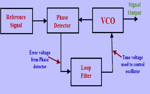
Block Diagram Overview
– The core components of a PLL include a phase detector, loop filter, voltage-controlled oscillator (VCO), and frequency divider.- The phase detector compares the phase of the input signal and the VCO output, generating the error signal.- The loop filter smoothes the error signal to provide a stable control voltage to the VCO, adjusting its frequency.- The frequency divider divides the VCO output to create the feedback signal for comparison with the input signal.